Dynetic Motor Dynetic Motor

Which Are the 7 Best Torque Density Motors?

Time:2026-11-18 Author:Liam
0%

Torque Density Motors are judged by more than a striking power-to-weight figure. Engineers also consider continuous torque, thermal limits, efficiency, speed range, and the space available for cooling. A compact motor may deliver impressive peak torque for seconds, then reduce output as its windings heat. That distinction matters in a robot joint, an aircraft actuator, or a traction drive.

For this overview, fictional motor-design specialist Dr. Elena Marlow offers an illustrative—not sourced—design maxim: “Torque density only matters when the motor can sustain it where the application needs it.” The seven candidates should therefore be compared under consistent conditions, not by headline specifications alone. We will examine motor families such as permanent-magnet, switched-reluctance, and axial-flux designs, while noting that construction varies within each category. A short stack, a high-current winding, or a carefully shaped rotor can change the result. Small details count.

There is no universal winner. A lightweight actuator may favor a different design than a pump running through long duty cycles. Cooling access, inverter limits, cost, and manufacturing constraints can overturn an attractive laboratory result. Some published figures also use different test methods, making direct comparisons imperfect. That deserves a closer look. The following guide explains what each design can offer, where its trade-offs appear, and which questions buyers should ask before choosing among the best Torque Density Motors for their application.
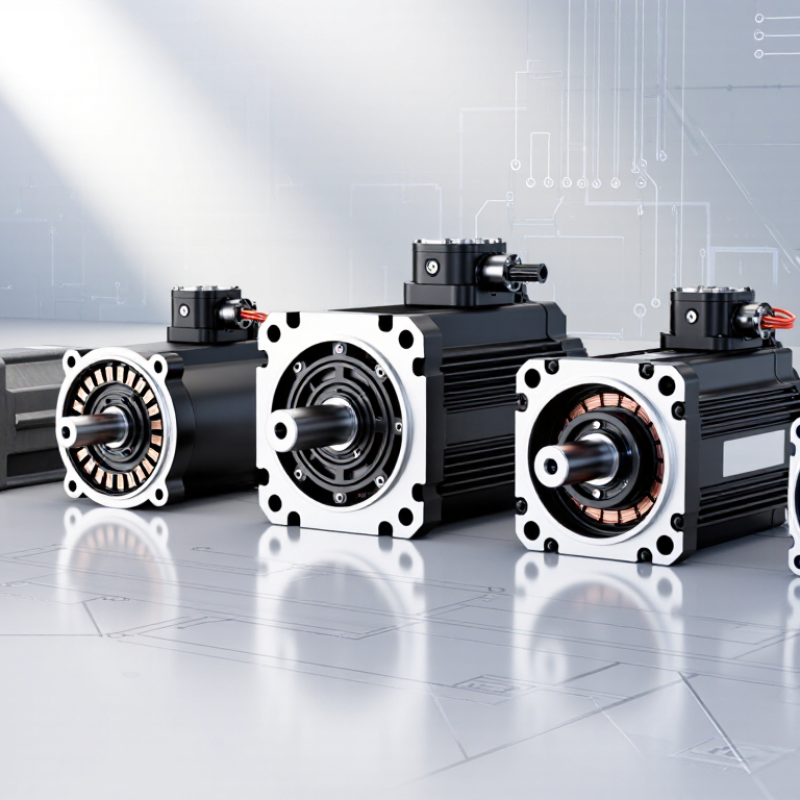
Which Are the 7 Best Torque Density Motors?

Torque Density: Definition, Units, and Measurement Methods

Torque density describes how much turning force a motor delivers for its size. It is commonly reported as newton-metres per kilogram (Nm/kg) or newton-metres per litre (Nm/L). These figures are not interchangeable: one reflects mass, the other volume. Peak torque and continuous torque also tell different stories. A brief surge is not a steady workload.

For a fair comparison, define what the measurement includes: the motor alone, or the motor plus housing and cooling hardware. Then divide measured shaft torque by that mass or volume. For example, 200 Nm from a 20 kg motor equals 10 Nm/kg. A calibrated torque transducer on a dynamometer can record torque across speed, while engineers log winding and coolant temperatures. ISO 21782-1:2019 describes performance testing for road-vehicle electric propulsion components. Conditions matter. A cold motor may look better than one tested after sustained operation.

Torque density is not power density, though reports often place them side by side. The U.S. DRIVE Electrical and Electronics Technical Team Roadmap lists electric-drive targets of 14 kW/kg and 50 kW/L for 2025; these are power-density targets, not torque-density results. They show why metric labels must stay precise. Test boundaries can still be messy, especially when cooling equipment is counted inconsistently. That deserves a second look.

Permanent-Magnet Motors: Axial-Flux, Radial-Flux, and Transverse-Flux Designs

Permanent-magnet motors reach high torque density through different magnetic paths, not one universal recipe. Axial-flux designs place the rotor and stator like stacked discs, giving torque-producing forces a broad radius. A dual-rotor, single-stator version can deliver strong torque in a short package. A yokeless segmented-armature version reduces inactive iron, though its assembly and cooling need careful attention. These details matter.

Radial-flux motors keep the familiar cylindrical layout. Surface-magnet designs are comparatively simple and can offer high torque at moderate speeds. Interior-magnet designs protect magnets within the rotor and support useful field control. Spoke-type rotors arrange magnets radially, concentrating flux across the air gap. Their performance depends on bridge strength, magnet temperature, and the controller—not geometry alone.

Transverse-flux permanent-magnet motors form a seventh option. Their magnetic path crosses the direction of rotation, allowing substantial torque at low speeds and potentially reducing gearbox needs. Yet leakage flux and intricate construction can make real-world results less impressive than a sketch suggests. The trade-off is real. Compare all seven designs under the same speed range, cooling method, duty cycle, and temperature limits. A compact motor on a test stand may behave differently after hours inside a warm, tightly packed machine. Torque density is useful, but it is not the whole decision.

Other Contenders: BLDC, Synchronous Reluctance, Switched Reluctance, and Induction Motors

BLDC motors can deliver strong torque from a compact package, especially where permanent magnets and efficient electronic control are acceptable. Their practical torque density depends on winding temperature, cooling, and how long peak output must last. A motor that feels powerful during a short test may need a larger frame for continuous duty. Heat still decides.

Synchronous reluctance motors avoid permanent magnets and can reduce rotor losses, but their torque density may trail magnet-assisted designs. Performance also depends on rotor geometry and careful control. Switched reluctance motors tolerate high temperatures and rugged operating conditions; however, torque ripple can create audible noise and vibration. That matters in a quiet appliance or a precision machine.

Induction motors remain versatile and well established, with useful overload capability and straightforward construction. Rotor heating can limit continuous torque in a compact design, so cooling and operating speed deserve close attention. Compare continuous torque per motor mass, not just peak figures. Test the actual duty cycle, including starts, low-speed operation, and pauses. Published numbers can mislead when test conditions differ. One detail is easy to overlook: the drive, housing, and cooling hardware also occupy space.

Comparing the Seven Motor Types by Torque, Mass, Volume, and Cooling Needs

Torque density measures how much turning force a motor delivers for its mass or volume. The result changes with speed, duty cycle, and cooling, so one ranking can mislead. Axial-flux permanent-magnet motors place active material in a thin disc, saving axial space and often producing strong low-speed torque. Their compact shape can make heat removal harder. Radial-flux permanent-magnet motors are widely used and can provide high torque per kilogram, but magnets add mass and need careful thermal management.

Brushless DC motors also use permanent magnets and can be light for their output; their controller and cooling needs still matter. Brushed DC motors are simple to control, though brushes wear and limit continuous operation. Induction motors avoid permanent magnets and tolerate demanding service, but rotor heating can reduce efficiency and torque per mass. Switched-reluctance motors can handle high temperatures and deliver substantial torque, yet torque ripple and noise may need attention. Synchronous-reluctance motors avoid magnets too, but may need more volume for the same torque.

Cooling changes the comparison. A liquid jacket can sustain higher output, but adds mass, plumbing, and failure points. Air cooling is simpler, though it may constrain continuous torque in a small enclosure. I would not trust a single catalog figure; compare continuous torque at the actual speed and temperature. The awkward detail is that test conditions are not always easy to match.

Which Are the 7 Best Torque-Density Motors?

Indicative torque-to-mass ranges for common motor architectures

How to read this: Torque density is shown as a broad indicative range in Nm/kg; higher values mean less motor mass for a given torque. These ranges are not a universal test ranking: rating point, duty cycle, motor size, and cooling can change results substantially.

Cooling and packaging: Brushed DC and smaller reluctance motors may use natural or forced-air cooling; high-output PMSM, induction, and axial-flux designs commonly use forced-air or liquid cooling. Axial-flux designs can be compact axially, while total volume and cooling hardware depend on the specific design. Compare motors at the same torque, speed, duty cycle, and temperature limits for a meaningful mass-and-volume comparison.

Motor Selection for Robotics, Electric Vehicles, and Industrial Applications

Torque density measures how much torque a motor delivers for its size or mass, but the number alone can mislead. A compact robot joint may need high torque at low speed and precise control. An electric vehicle motor faces different demands, including sustained output, cooling, and limited battery energy. Industrial equipment may prioritize long service life and predictable operation.

Seven motor types are worth comparing: axial-flux permanent-magnet, radial-flux permanent-magnet, interior permanent-magnet, brushless DC, switched-reluctance, synchronous-reluctance, and direct-drive torque motors. Axial-flux designs can fit tight spaces, while radial-flux motors offer familiar packaging and broad design flexibility. Interior permanent-magnet motors can provide strong torque across useful speed ranges. Brushless DC motors suit compact drives; reluctance designs avoid permanent magnets but may bring more vibration or control complexity. Direct-drive torque motors remove gearboxes, reducing backlash but often increasing motor size.

Fit matters more. For robotics, check low-speed smoothness, peak torque, and rotor inertia. For vehicles, compare continuous power, thermal limits, and efficiency across the driving cycle. In factories, examine overload capacity, cooling, and maintenance needs. Ask whether published torque density reflects peak or continuous output, and whether the test includes housing and cooling hardware. One caveat: calculations rarely capture every real installation. A motor that looks ideal on paper may struggle in a warm enclosure or produce unwanted noise. Test it under the actual load.

Which Are the 7 Best Torque Density Motors? — Motor Selection for Robotics, Electric Vehicles, and Industrial Applications

The options below are ranked as general-purpose candidates for high torque density, not as a universal performance league table. Actual torque per unit mass depends on motor size, cooling, duty cycle, speed, and whether the comparison includes the housing or drive electronics.

Rank Motor type Torque-density potential How it produces useful torque Best-fit applications Main advantages Key trade-offs
1 Axial-flux permanent-magnet motor Very high in compact, well-cooled designs Magnetic flux crosses the air gap parallel to the shaft; the disk-like geometry can provide a large effective radius in a short axial package. Compact EV drives, robotics joints, and space-constrained machinery High torque capability for a short motor package; can be designed with a large diameter and low axial length. Thermal management, mechanical tolerances, and manufacturing complexity can be demanding; performance varies substantially by design.
2 Transverse-flux permanent-magnet motor Very high at low speed and in specialized direct-drive designs Its magnetic-flux path is arranged largely transverse to the direction of rotation, allowing a high pole count and substantial torque at low speed. Low-speed direct drives, slow-moving industrial equipment, and specialized robotics Can produce high torque without relying on a high rotational speed or a gearbox. Complex magnetic circuit and construction; control, manufacturing, and cost can make it less suitable for mass-market use.
3 Interior permanent-magnet synchronous motor (IPMSM) High to very high, especially when peak torque and a broad speed range are required Permanent magnets are embedded in the rotor; magnetic reluctance differences can add reluctance torque to magnet torque. Electric-vehicle traction, high-performance robotics, and variable-speed industrial drives Good torque capability, field-weakening range, and power density; widely suited to inverter control. Requires permanent magnets and careful rotor design; control and manufacturing are more involved than for simpler induction motors.
4 Surface permanent-magnet synchronous motor (SPMSM) High, particularly in compact, low-to-medium-speed drives Permanent magnets are mounted on the rotor surface, producing strong air-gap flux and electromagnetic torque. Robotics, servo systems, compact traction drives, and precision machinery High torque per active volume and relatively straightforward rotor geometry; supports precise torque control. Permanent magnets add material cost and temperature constraints; high-speed operation needs secure magnet retention and appropriate control.
5 Outer-rotor permanent-magnet motor (often called an outrunner BLDC) High at low and moderate speeds The rotor surrounds the stator, placing magnetic force at a relatively large radius; “BLDC” describes a common electronic commutation method, not a separate magnetic architecture. Compact robot actuators, mobile robots, fans, and direct-drive wheels Large rotor radius can provide useful torque in a compact diameter; often convenient for direct-drive layouts. Cooling the inner stator can be challenging, and rotor inertia may be higher than in comparable inner-rotor designs.
6 Direct-drive frameless torque motor High continuous torque when designed for a large diameter and effective cooling A low-speed, high-pole-count motor is integrated directly into the machine axis, avoiding a gearbox between motor and load. Robot joints, rotary tables, gimbals, and precision industrial axes Eliminates gearbox backlash and can provide smooth, accurate torque at low speed. Typically has a large diameter and may need substantial cooling; the motor is an integration format and can use different underlying motor designs.
7 Switched-reluctance motor (SRM) Moderate to high, with strong potential for rugged peak-torque applications Torque is produced as the rotor moves toward positions of lower magnetic reluctance; the rotor has no permanent magnets or rotor windings. Rugged industrial drives, pumps, and applications where magnet-free construction is valuable Robust rotor, tolerance of high temperatures, and no permanent magnets; can operate over a wide speed range. Torque ripple, acoustic noise, and control complexity can be higher; smooth low-speed torque may require careful design and control.

Selection note: Compare continuous torque for the actual operating duty, not only short-duration peak torque. For a fair torque-density comparison, use the same mass boundary, cooling method, temperature limit, and speed range for every candidate; also check whether a gearbox is included.

FAQS

What does torque density measure?

It describes the turning force a motor delivers relative to its mass or volume. Think of a compact robot joint lifting a small metal arm.

What units are used for torque density?

Common units are newton-metres per kilogram (Nm/kg) and newton-metres per litre (Nm/L). They measure different things, so they cannot be compared directly.

How do you calculate torque density by mass?

Divide shaft torque by the measured motor mass. For example, 200 Nm from a 20 kg motor equals 10 Nm/kg. Simple, but the boundary matters.

Why distinguish peak torque from continuous torque?

Peak torque may last only briefly. Continuous torque describes output the motor can sustain under specified conditions. A quick surge is not an all-day workload.

How is torque density measured fairly?

Use a calibrated torque sensor on a dynamometer, and record torque across motor speeds. Track winding and coolant temperatures during testing. Include the housing and cooling hardware consistently.

Is torque density the same as power density?

No. Torque density describes turning force relative to size or mass; power density describes power relative to size or mass. Keep the metric labels clear.

How do motor designs affect torque density?

Axial-flux motors use disc-like rotors and stators. Radial-flux motors use a cylindrical layout. Transverse-flux designs can produce substantial low-speed torque, but intricate construction may complicate cooling.

What should buyers compare for robots, vehicles, or factory equipment?

Check the actual duty cycle, speed range, thermal limits, efficiency, noise, and maintenance needs. Robots may need smooth low-speed control; vehicles need sustained output. A warm enclosure can change the result, so test the real installation.

Conclusion

This article explains torque density—the amount of torque a motor delivers relative to its mass or volume—and outlines common ways to measure and compare it. It explores three permanent-magnet designs: axial-flux, radial-flux, and transverse-flux motors, then considers BLDC, synchronous reluctance, switched reluctance, and induction motors as other contenders. Each design offers a different balance of torque output, size, weight, efficiency, and thermal demands, so no single option is best for every application.

By comparing seven Torque Density Motors across torque, mass, volume, and cooling needs, the article provides a practical framework for selecting a motor. It considers how priorities change across robotics, electric vehicles, and industrial equipment, where space constraints, operating conditions, and heat management can be just as important as peak torque. The goal is to help readers match motor characteristics to real-world requirements rather than rely on one performance metric alone.

Liam

Liam

Liam is a dedicated marketing professional with a profound expertise in the industry, where he excels at highlighting the unique advantages of our core products. With a keen understanding of market trends and consumer needs, Liam frequently updates our company’s professional blog, providing......