Dynetic Motor Dynetic Motor

BLDC DC 5-36v Brushless Sensorless Motor Control Board Driver

Product Description

Governor Panel and Connection Details

1. Electrical Performance Specifications

  • Voltage Range: DC 5V - 28V
  • 🔌
    Rated Current: MAX 2A. To control the motor with greater current, connect the motor power line directly to the power supply, bypassing the governor.
  • 📊
    PWM Output Frequency: 0 ~ 100KHz
  • 📉
    Analog Voltage Output: 0 - 5V
  • 🌡️
    Temperature Limits: Working -10℃ to 70℃ | Storage -30℃ to 125℃
  • 📏
    Driver Board Size: Length 60mm X Width 40mm

2. Governor Wiring & Internal Functions

1
Governor, motor power supply positive input.
2
Governor, motor power input negative.
3
The positive output of the power supply of the motor.
4
Negative output of the power supply of the motor.
5
High/low level output of positive/negative rotation control (High: 5V, Low: 0V). Controlled by touch switch 2 (F/R), default is high level.
6
High/low level output of brake control (High: 5V, Low: 0V). Controlled by touch switch 1 (BRA), power on default is high level.
7
Analog voltage output (0~5V). Suitable for motors accepting analog voltage speed regulation.
8
PWM1 reverse output. Speed is inversely proportional to the duty cycle.
9
PWM2 forward output. Speed is proportional to the duty cycle.
10
Motor feedback signal input.
Information & Tuning: The output signal changes of the three interfaces (7, 8, and 9) are adjusted by the potentiometer.

Note: FG/FG*3 should be based on the actual motor feedback times to determine whether to add a jumper cap. No jumper cap signifies single times FG; an added jumper cap increases this to 3 times (FG*3). The same principle applies to CW/CCW setup.

3. Governor Parameter Settings

⚙️ Frequency Setting
Press and hold touch switch 1 before power-on. Supply power to the board and release when the screen displays "FEQ:20K". Touch switch 1 to reduce and switch 2 to increase. The factory default value is 20KHz.
⚙️ Number of Poles Setting
Before powering on, hold down touch switches 1 and 2 simultaneously. Power the board and release when "number of poles: 1 polarity" displays. Press switch 1 to decrease, or switch 2 to increase. Default is 1 pole.
⚙️ Feedback Setting
The FG/FG*3 pin sets the feedback multiplier. If your motor requires a single FG feed, leave the jumper cap off. Add the jumper cap to configure it to 3 times feedback multiplier (FG*3).
⚙️ Direction & Main Display
Direction: The CW/CCW pin sets the initial motor direction when the control line is suspended. Add a skip cap for CCW; leave off for CW.
Main Screen: Displays input voltage, speed, frequency, and duty cycle. The speed display relies on accurate FG/FG*3 and pole number configuration.
⚠️ Important Precautions
1. Power Input Polarities: The positive and negative power supply of the governor must be connected exactly as instructed. Reversing the polarity will burn the governor and render it inoperable.
2. Motor Matching: The governor is designed to match motors utilizing the control interfaces described.
3. Voltage Limits: Ports 5 through 9 cannot accept voltages exceeding 5V.

💡 Frequently Asked Questions

❓ Q1: What is the maximum current this governor can handle?
A1: The rated current is MAX 2A. If you need to control a motor requiring a higher current, you should connect the motor power line directly to your power supply instead of routing it through the governor.
❓ Q2: What happens if I reverse the power supply connections?
A2: The positive and negative power supplies must be connected in accordance with the specifications. Reversing these inputs will damage and burn the governor board.
❓ Q3: How do I adjust the PWM frequency limits?
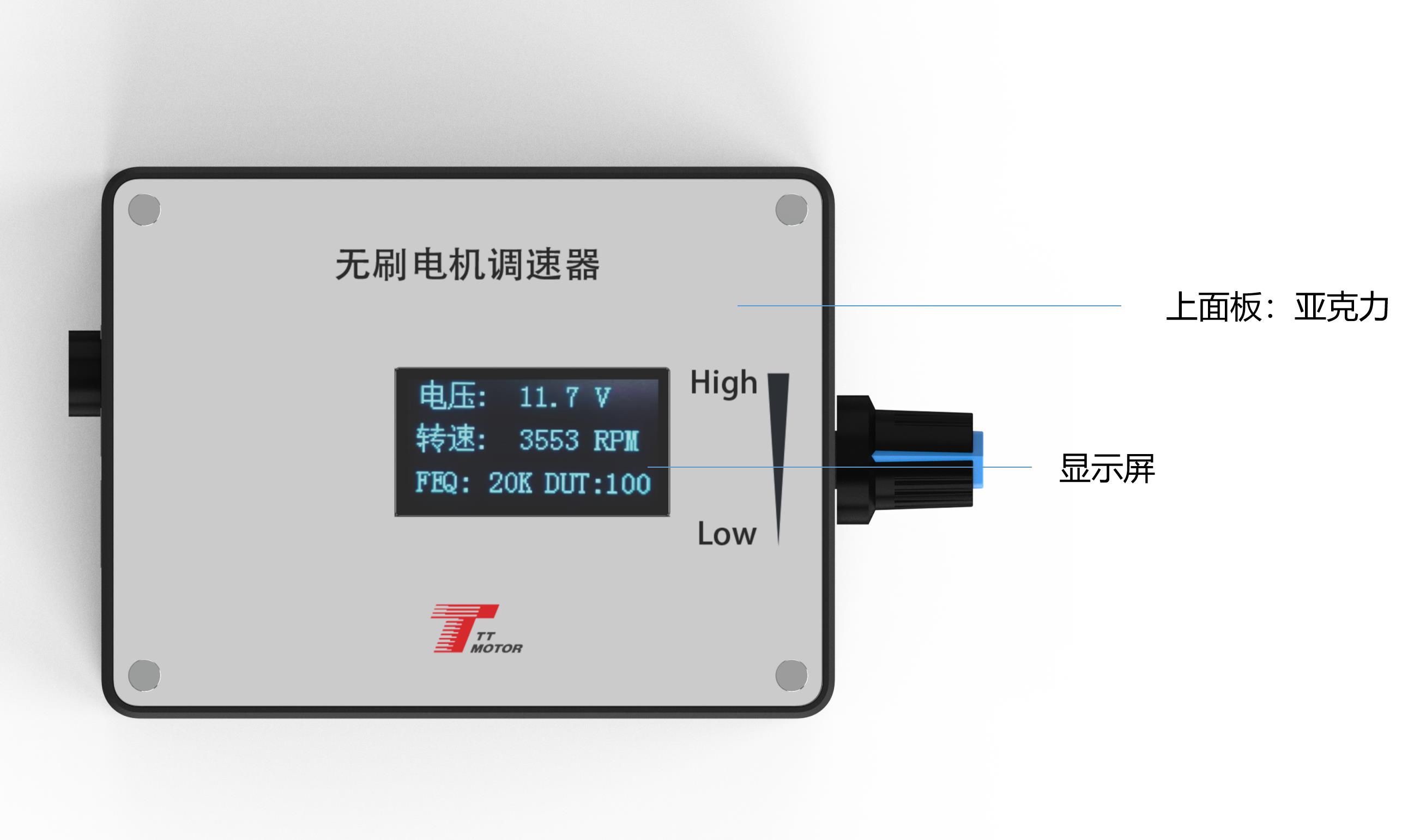
A3: Hold down touch switch 1 before powering on, then turn on the power. Release the button when "FEQ:20K" appears. You can then use touch switch 1 to decrease frequency and touch switch 2 to increase it. The factory default is 20KHz.
❓ Q4: How do I set the number of poles for the motor?
A4: Hold down both touch switch 1 and 2 before powering on the board. Once the screen shows "number of poles: 1 polarity", release the buttons. Use switch 1 to decrease and switch 2 to increase (factory default is 1 pole).
❓ Q5: When should I add a jumper cap to the FG/FG*3 or CW/CCW pins?
A5: For feedback, leave the jumper cap off for a single times FG feedback, and add it for 3 times FG*3 feedback. For direction, add the jumper cap to configure initial state to CCW, or leave it off to default to CW.
❓ Q6: What is the voltage limit for the control signal ports?
A6: Control ports 5 through 9 cannot handle inputs exceeding 5V. Please ensure your control signals conform to this safe limit.

Related Products