1 / 5

Governor, motor power supply positive input.
Governor, motor power input negative.
The positive output of the power supply of the motor.
Negative output of the power supply of the motor.
High and low level output of positive/reverse rotation control. High: 5V, Low: 0V. Controlled by touch switch 2 (F/R), default is high level.
High and low level output of brake control. High: 5V, Low: 0V. Controlled by touch switch 1 (BRA), power on default high level.
Analog voltage output (0~5V). Suitable for motors accepting analog voltage speed regulation.
PWM1 reverse output. Suitable for motors accepting PWM speed regulation (speed is inversely proportional to duty cycle).
PWM2 forward output. Suitable for motors accepting PWM speed regulation (speed is proportional to duty cycle).
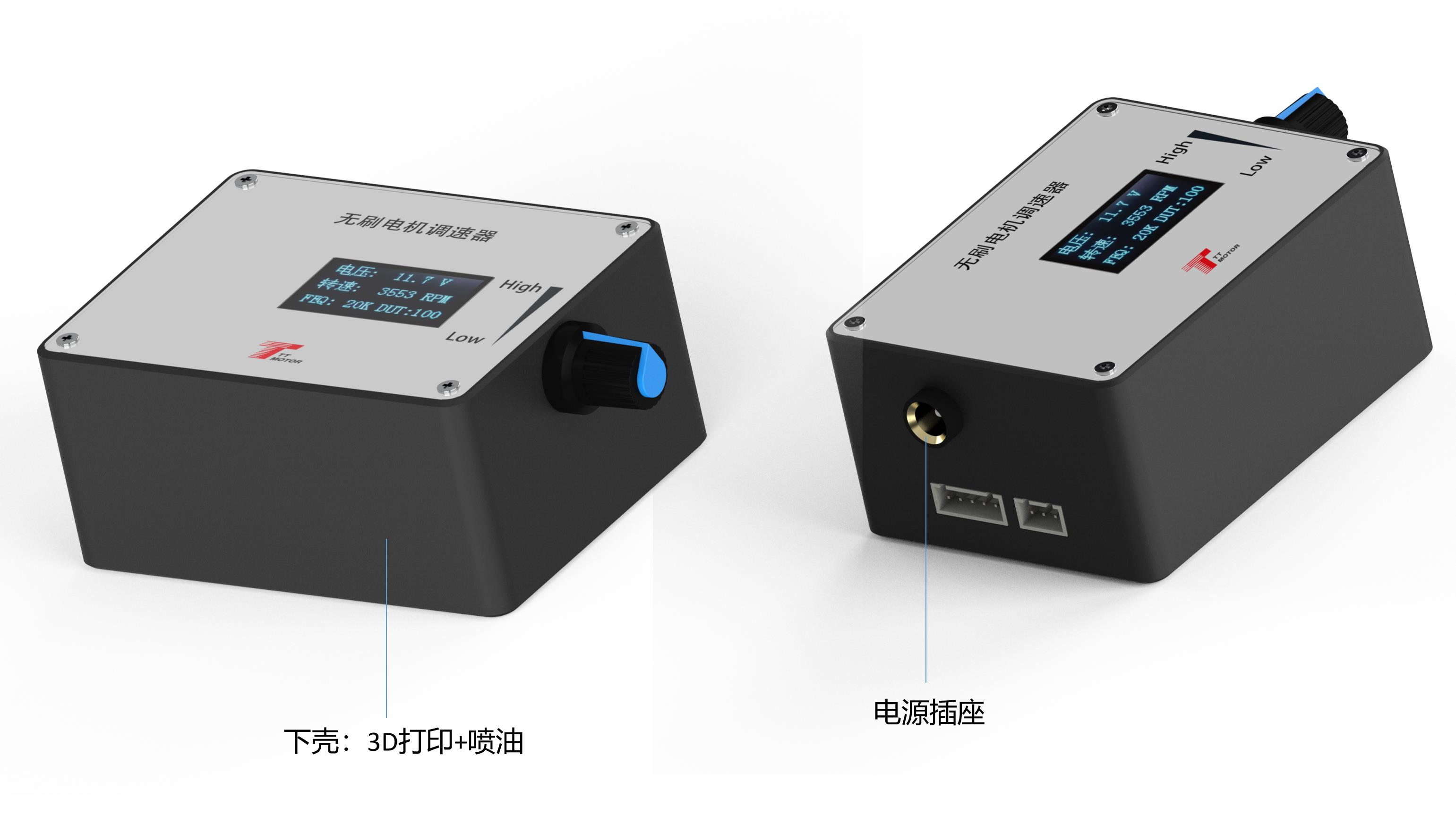
The output signal changes of the three interfaces are adjusted by the potentiometer.
Motor feedback signal input.
Press and hold touch switch 1 before powering on. Connect power to the board and release the switch when the screen displays "FEQ:20K". Touch switch 1 to decrease, and touch switch 2 to increase the frequency. Adjustable to specified frequency (factory default: 20KHz).
Press and hold touch switch 1 and 2 simultaneously before powering on. Connect power and release switches when the screen shows "number of poles: 1 polarity". Touch switch 1 to decrease, and touch switch 2 to increase. Configure to match your motor design (factory default: 1 pole).
Refer to FG/FG*3 pin setup. Set according to whether the feedback multiplier of the motor is single FG or three times FG. Add jumper cap for 3 times FG; remove jumper cap for single FG.
Refer to CW/CCW pin setup for initial state direction. Configure depending on whether the motor runs CW or CCW when the direction line is suspended. CCW requires the skip cap added; CW requires no skip cap.